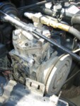
Most A/C compressors lubricate themselves with the freon that flows through the A/C system. In order to use these compressors for pumping air, you need to have an external oiler feeding air into the intake hose and a filter to remove the oil from the output hose. Certain York-style compressors (the big, boxy, vertical kind) used an internal oil reservoir for lubrication, which makes them ideal for use as stand-alone air compressors.
Although the York has a separate oil reservoir, it still leaks some oil back into the discharge line. This is nice if you’re running air tools, but you really don’t want to be pumping all that oil into your air tank or your tires. For over 6 years, I got around this problem by under-filling the oil in my compressor — as little as a single ounce of 10W30. The proper oil level is actually 8-12 ounces. Under-filling worked OK, but the compressor got pretty hot when used for any length of time.
There are two ways you can get around this problem without oil-starving your compressor. The first method is to put an inline oil separator on your discharge line, then plumb the separator’s drain port back to your compressor’s oil fill hole. This is probably the proper way to solve the problem, but it adds a lot of expense an a lot of extra plumbing to your OBA setup. If you’d prefer this route, Kilby sells all the necessary equipment.
The second solution (and the one I chose to implement) is to modify the York to reduce its oil discharge, supposedly without adversely affecting its internal lubrication. I’d heard rumors of this mod for years, but the first decent writeup I saw was on SuperFord.org (no longer active). Essentially, you partially dismantle the compressor and then plug an internal oil passage with a small set screw.
More than 6 years after I first setup my York on-board air, I modified my compressor via the second method. The following includes photos and some caveats that I encountered along the way.
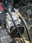
- First, you must remove the pulley from the compressor. If your compressor is currently mounted in the vehicle, I recommend you leave it there for now. Having the compressor securely mounted will help you loosen some stubborn bolts. If you can short the clutch wire to the positive battery terminal to keep the clutch engaged while you’re trying to unbolt the pulley, it’ll really help. If not, you’ll have to use a strap wrench or something else to keep the pulley from turning while you wrench on the bolts. If you have access to an impact wrench, use it! It’ll make the bolt removal much easier than trying to slowly use a wrench while keeping the pulley stationary.
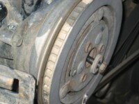
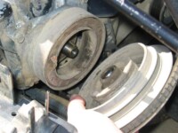
To remove the pulley, you first use a 1/2″ socket to remove the retaining bolt & washer from the center of the pulley. This bolt threads into the center of the compressor’s crankshaft to hold the pulley in place.
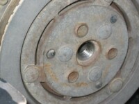
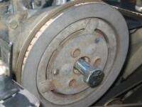
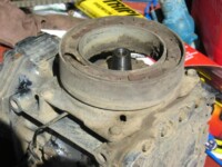
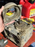
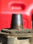
Once the retaining bolt is out, you’ll see threads exposed inside the hole in the pulley. Screw a 2″ long, 5/8″ coarse thread bolt into those threads. Once that bolt bottoms against the end of the crankshaft, screw it a little bit farther to force the pulley off the shaft. The shaft is tapered, so once the pulley breaks free, it’ll pretty much just fall off. This only took a split second using my impact wrench. 🙂 - Next, remove the clutch from the compressor body. If the compressor is still in the vehicle, make sure the clutch wire has been unplugged. The clutch is secured to the compressor body using four bolts with a 3/8″ head. On mine, these were too stubborn for a small wrench, but the impact wrench once again made short work of removing them. (Notice a theme here? Air tools make work easier. Having them available for trail repairs will really help. Aren’t you glad you’re installing on-board air?)
If your compressor is still attached to the vehicle, you can remove it now and relocate it to a clean workbench.
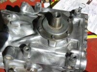
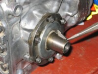
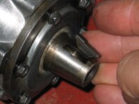
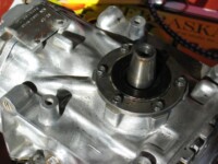
If you never were quite sure what displacement your compressor was, now is an easy time to check. Look at the end of the crankshaft. If the outer edge is beveled, it’s a 6ci model. If the outer edge has a groove for a retaining clip, it’s a 9ci model. If the outer edge has a sharp corner with no groove, it’s a 10ci model. - Next, you must remove the woodruff key from the shaft so that you can later take the bearing seal off. To do this, take a large screwdriver, a brass drift punch, or some similar object and put it against the outer end of the key. Using a BFH, drive the key toward the body of the compressor. Don’t whack it so hard that the key shoots off to Never Never Land, though. That would really ruin your day. The slot for the woodruff key is half-moon shaped, so as you drive the key lengthwise along the shaft, the key will be forced out of the slot.
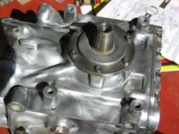
- If you haven’t already done so, you’ll now want to make sure that the front of your compressor body is pretty clean. You don’t want any dirt or crud falling into the compressor bearings after you remove the crankshaft seal. I went hog wild with this. Instead of just removing loose crud, I used a wire wheel and a power drill to strip the entire compressor down to shiny, bare aluminum. It looks much nicer now. I considered polishing it to a mirror finish, but figured that’d be overkill. Just for good measure, I also shot the clutch bracket and pulley with a quick coat of semi-gloss black Rustoleum paint. Looks like I’ve got a new compressor now!
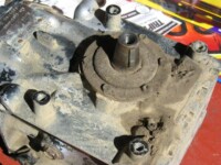
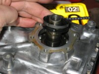
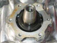
- Next, remove the six retaining bolts from the seal retaining plate using a 1/4″ wrench. Pull the dust cover and retaining plate off the shaft and carefully lay them aside. There’s an odd rubber seal on the bottom side of the retaining plate. In my case, it stuck to the bottom of the plate when removed.
- Next, remove the seal spring from the shaft. You’ll need a small screwdriver to lift the spring out of the bearing cavity. The top of the spring has a metal plate with four notches in it. The rubber seal under the retainer plate has four notches to fit into these grooves. Make sure they line up upon reassembly.
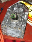
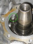
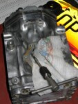
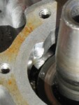
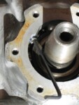
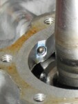
- Now the fun part begins. As you look at the front of the compressor body, you’ll see two ribs that run diagonally from the crank seal area toward the suction and discharge ports at the top of the compressor. One of these ribs (the one going toward the suction port, whichever side that’s on for your compressor) has a oil galley in it. If you look at the inner wall of the seal cavity, you’ll see the hole where oil is sucked from the seal area toward the main suction port. By plugging this hole, you’ll prevent most of the oil from being discharged from your compressor. The original purpose of this galley is to act as a return line for oil that’s sucked into the seal cavity through the bearing from the crankcase. The oil then passes from the suction port through the compressor and out the discharge port into your air line. One might think that plugging this hole (and thereby removing the suction from the seal cavity) would prevent fresh oil from being sucked through the bearing and would eventually dry out the seal. I’ve heard no reports of such a problem, though.Before the surgery begins, lightly coat a rag or paper towel with water or oil or something, then shove it down into the seal cavity around the shaft. You want to catch all the metal filings before they fall into the bearing. The water/oil coating helps the filings stick to the rag/towel.
- Find a 10-32 thread tap and see what size drill bit it recommends using. Mine said either #21 or 4.05mm, which is just a shade larger than 5/32″, but close enough. This is only slightly larger than the original size of the hole, so you won’t be removing much material. With the bearing completely protected by your rag, drill about 3/8″ deep into that oil hole, or a little bit deeper than the length of your set screw. Note that the hole runs parallel with the rib in the compressor body, which runs diagonally downward and outward from the little opening in the seal cavity.
- Using your aforementioned 10-32 thread tap, cut threads into the hole you just drilled. Make sure your threads are deep enough that the end of your set screw will be flush with (or slightly recessed into) the inner wall of the seal cavity, yet still shallow enough that the screw will bottom against the end of the threads for a tight fit before it gets recessed too far into the hole. When done, VERY CAREFULLY remove the rag/towel that was catching all the metal filings. If any filings fall out into the bearing or won’t come out of the oil hole, use a vacuum to remove them rather than driving them in with compressed air.
- Put some Loc-tite on your set screw so that it doesn’t back out, then install the screw into the hole. These set screws are available in a variety of lengths from any decent hardware store. I got one that was 5/16″ long. Mine required a 3/32″ allen wrench to install it.
- Install the seal, making sure that notches in the rubber match the metal plate.
- Install the seal retaining plate & dust shield and tighten the retaining plate bolts to 5-8 ft-lbs. Make sure you don’t forget the dust shield like I did. I had finished reassembly when I discovered it under a rag on my workbench, then had to take everything apart to put it back on.
- Drive the woodruff key back into its slot on the crankshaft.
- Install the clutch and tighten the brackets bolts to 13-19 ft-lbs.
- Slide the pulley back onto the crankshaft, making sure to line up the woodruff key with the notch in the pulley. It might be a good idea to make a mark on the pulley’s center section to indicate the orientation of the woodruff key so you know where it is when using the dip stick described below. Tighten up the pulley by torquing the center retaining bolt to 20-25 ft-lbs. Reinstall the compressor in your vehicle.
If you haven’t already done so, empty all the old oil from your compressor and refill it with fresh oil. The standard York has an oil fill/check hole in the center of each side of the compressor body. The York I got from a Ford had one of those holes plugged (that side was unreachable in the factory mounting location), so only the right side hole was usable. When fully filled, a York used as an air (not A/C) compressor requires 8-10 ounces (237-296 mL) of oil. The type of oil isn’t critical when pumping plain air w/o freon; regular old 10W30 or ATF will work fine (I used ATF). A trigger-type oil squirt can seems to be the best way to add oil when necessary. To check the oil level, I recommend using a dip stick as described on page 7 of this section of the York service manual. It’s a PDF file, so you’ll need to have Adobe’s Acrobat Reader installed in order to view the file. You’ll need to rotate the crankshaft to get the crank journals out of the way of the dip stick. When using the right side fill hole like I am, you want the crank’s woodruff key to point upward.
Do you like this site?
Help me keep it going by throwing a few pennies my direction.
![]()
![]()
![]()
![]()
Links on this page to Amazon are part of an affiliate program that helps keep Jedi.com operational.
Thank you for your support!


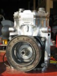
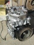
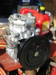
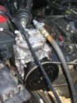
Thanks for the info I found this very helpful. I didn’t use the 10-32 set screw, instead I used a 8-32. I found that the hole dia was close to the 8-32 form tap (or roll tap) dia, so I gave it a shot. It seemed to work. The advantage to the form tap was I didn’t have to drill it out (so no drill shavings to get in the bearings, and the roll tap doesn’t make any chips either). Thanks again.
John, that’s good to know. Thanks for the tip! I’d never heard of a roll tap until just now. It sounds like a great too to use in soft materials like aluminum. If you don’t already have a set of taps and have to buy one anyway for this job, it would probably be good to find a roll/form tap instead of a cut tap.
This is an awesome write-up, thank you. I’m curious if you have a guess as to how long you’ve been running this mod and if you’ve had any adverse effects yet? Basically, before I get into this (adding to my 6.7l Powerstroke) I’d like to know if I’m going to be causing myself some headache later. Thanks a ton.
Howdy Robert. I performed this oiling mod in 2004, so it’s been there for 16 years as I write this. I’ve never noticed any adverse effects, and the York still pumps very well. That said, I really haven’t used it very frequently for the last 10 years or so, so I’m not a very good test case for stress testing this operation.
Hi, I have a quick question. My York 210 seems to have another oil passage. Its on the same side as this one right by the other piston. Does yours have this? Do I need to cover this one up too?
Hey Armen,
I see (from the photo you emailed me) that you’re looking at the compressor from the top after the cylinder head has been removed. I’ve never removed my cylinder head before, so I can’t say precisely what that tiny hole is. I am sure, though, that the only hole you want to plug for this mod is the one by the pulley shaft. You can safely ignore that other hole.
Nice write up!! Thinking outside the box… JB Weld? Has anyone tried it? Not shavings and “should” hold up.
JB Weld is an interesting idea. I’ve never heard of anybody using that. I can’t think of a reason why it wouldn’t work, though.
You’d want to make sure it was secured well to the hole, because if a chunk of it came loose, it could ruin your compressor.
JB Weld is resistant to all petroleum products.
JB Weld can withstand a constant temperature of 500F, which should be plenty unless your compressor is about to seize up anyway from lack of lubrication.
If you decide to use JB Weld to plug that hole, please report back here and let us know how it worked out!
LOL… “No shavings”
Completed the mod using JB Weld. A couple things to note:
1. Score the suction tube a little as JB Weld like a bit of a “rough” serface to stuck to
2. I use a heat lamp to help cure the JB weld, watch it for a bit, once it warms enough to “flow” stand the compressor up so it doesn’t flow into the head. I put a paper towel under the port to catch any “drip”. It stopped flush to the surface.
Now time will tell on if I end up with a slug in the gut for the compressor or a proper plug for the tube.
Thanx for a great write up!!
Thanks for the excellent write up and for the sharing of ideas here. I also elected to use JB Weld for my compressor. I use it in many different applications and am comfortable with it’s temperature resistance and adhesion performance. As Kevin mentioned, I scored the inside of the hole to help provide some tooth for adhesion. I mixed it without heat. I used a small wooden mixing stick to force plenty of JB Weld into the hole and spread it smoothly over the top of the hole. It’s perfectly flush with the rest of the housing and looks great. I’ll report back if I have any long term issues. Thanks again.
I recently installed a york 210 on my GMC Duramax and what worked best for me was to plug the oil hole going into the suction side of the compressor, then I drilled a hole in one of the oil plugs and bolted it through a small metal container with some scotch bright padding in it and holes in the lid. Now I get very minimal amount of oil in the tank. I have pictures of what I did and would have no problem sending to anyone that wants to see it.
That’s interesting. So your theory is that the oil system is pressurized, and you’ve created a sort of PCV valve for the compressor’s oil system so that the oil is less likely to get injected into the air line? Or am I confused? Either way, I’d love to see some pictures of what you did. Do you get much oil in your new container?