Table of Contents
Tear Down / Inspection
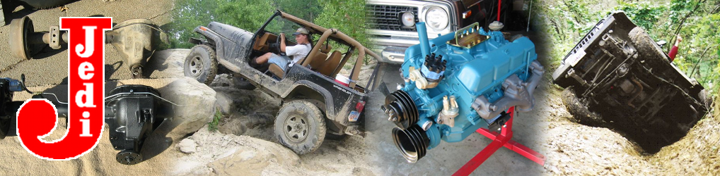
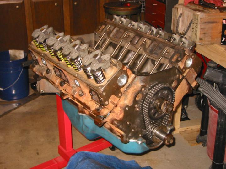
I’ll write this section someday. The heads, like the rest of the engine, were a basket case. 1974 heads on a 1977 engine, mixed parts, and mismatched machine work were the highlights.
Left head ID stamped into casting
Do-It-Yourself Head Porting
 When rebuilding the AMC 401 V8 from my ’77 Jeep Wagoneer, I figured that as long as I had it all ripped apart, I wanted to put it back together right rather than doing it just good enough to run for a few more miles. This mean upgrading several pieces to better-than-stock form, including the cam, water pump, and most importantly, the cylinder heads. I paid my machinist (Matt at Richards Machine) to press in new valve guides (the old ones were very worn) and new powdered metal valve seats (the old seats in my ’74 heads weren’t made to stand up to the abuse of today’s unleaded fuels) and to do a 3-angle valve job.
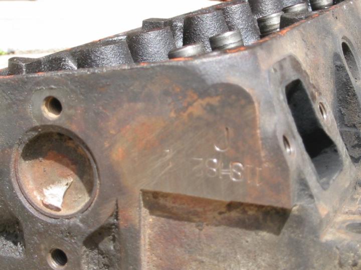
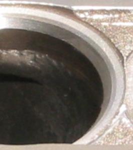
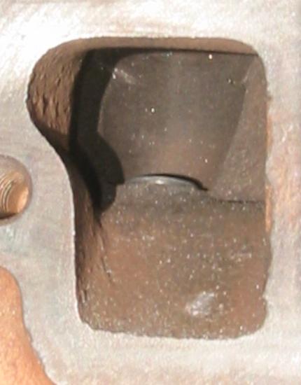
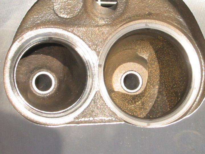
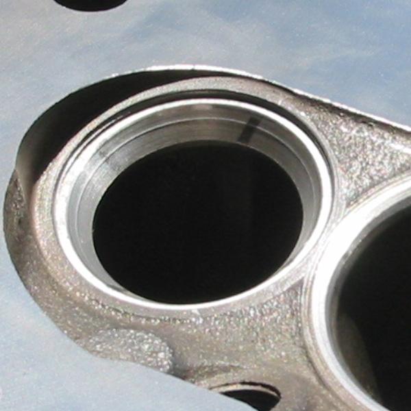
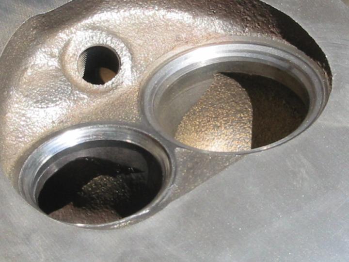
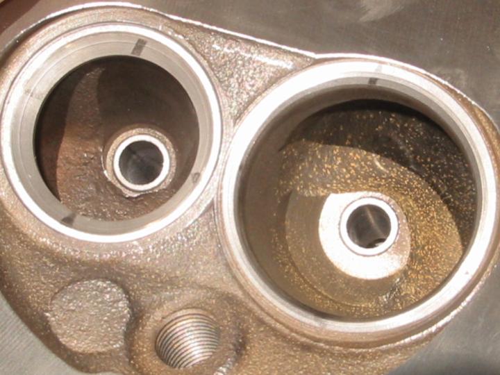
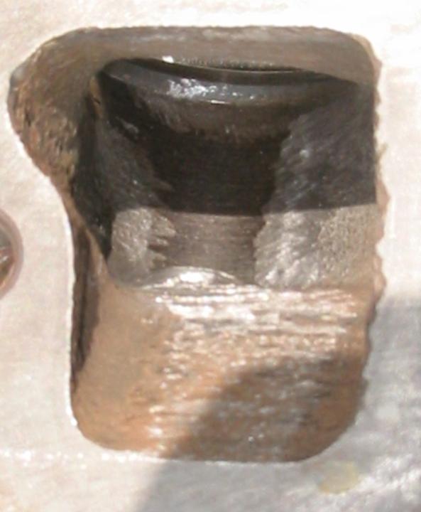
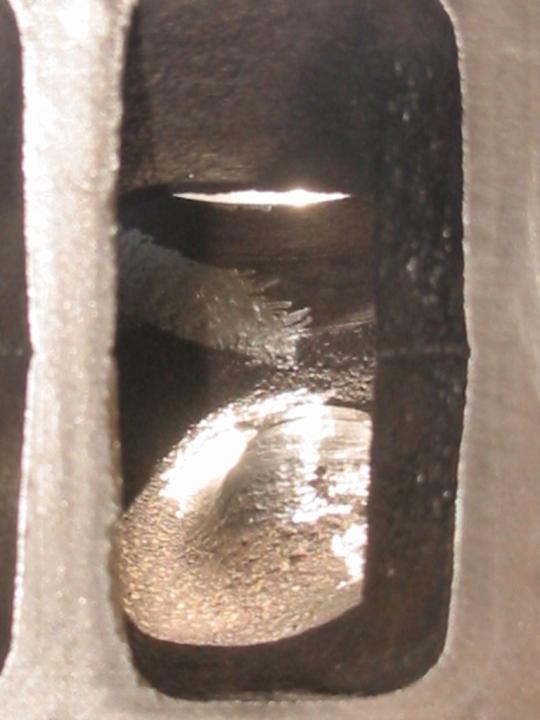
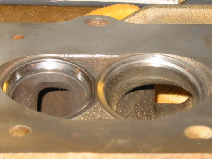
According to all the experts, getting a 3-angle valve job is the single best way to improve the air flow in stock cylinder heads. However, one look into the factory cylinder heads at the sharp edges and shrouded areas around the valve stem bosses made it obvious that even the simplest porting job would yield significant improvements in air flow. Armed with tips from Vizard’s book and a Dremel tool with a carbide cutting bit, I decided that was something I could probably handle myself. I wasn’t thinking of an all out, race ready port and polish job, mind you, just rounding off the corners and hard edges to produce a smoother contour and better air flow without significantly changing the port volume. Besides, at the speeds my engine will usually run (less than 4000 rpm), what matters is shape, not finish. A little roughness on the port walls is even desired on the intake ports, since the air turbulence it causes mixes the fuel and air better.
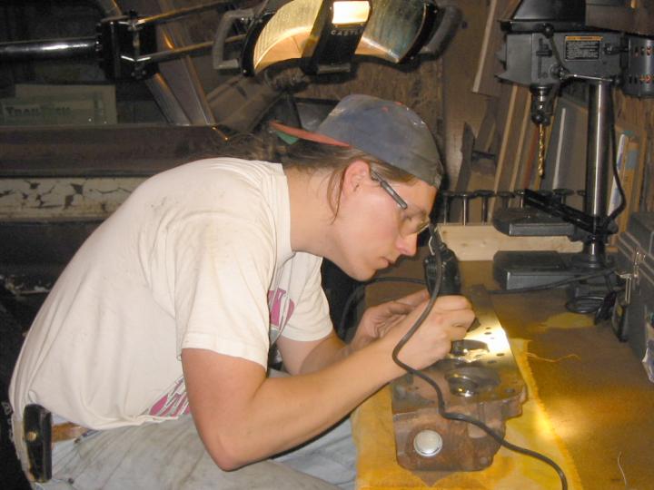
 When I first started, I didn’t know just how much time I should expect to spend on this job. It ended up taking me roughly 12 hours to port both heads — about 45 minutes per valve, on average. Most of the work involved smoothing the edges where the new valve seats joined the heads, as well as significant material removal to round off the valve guide bosses. The latter is the area where the factory castings needed the most obvious improvements. While I smoothed out some of the largest casting imperfections in the main port runner, I left most of those areas largely untouched. If the process had gone faster, I might have taken the time to put a smoother finish on the exhaust ports, since rough surfaces increase carbon buildup. After 12 hours, though, I figured I’d done enough. As an aside, the movable light that you see over my shoulder in the photo at top was sure handy during this job. My neighbor used to give tattoos, and had one of those dentist-style lights that he could swing around to any position to light up his work area. When he quit the business and moved, he gave me the light.
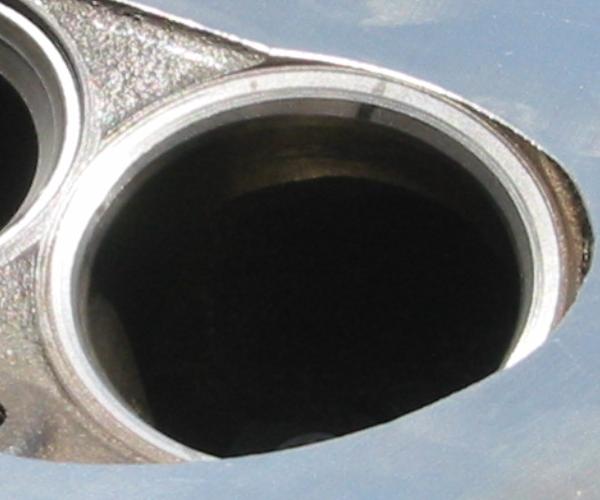
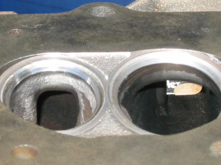
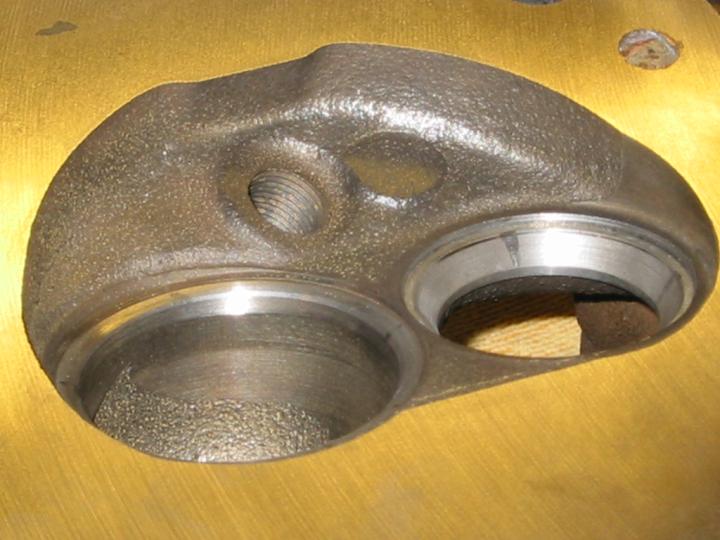
The resulting port shape certainly looks and feels smoother and more aerodynamic, and I’m generally happy with the way things turned out. The real test will come when I’ve got the new engine at wide open throttle, of course. I won’t be able to do any detailed comparison with the old setup, unfortunately, since I’ve also installed a new cam and fixed the old (previous owner’s) carb mounting setup that prevented the secondary valves from opening more than a crack. I’m sure the combination of all my upgrades will make the power difference like night and day.
Maybe I’ll put a diagram here someday.

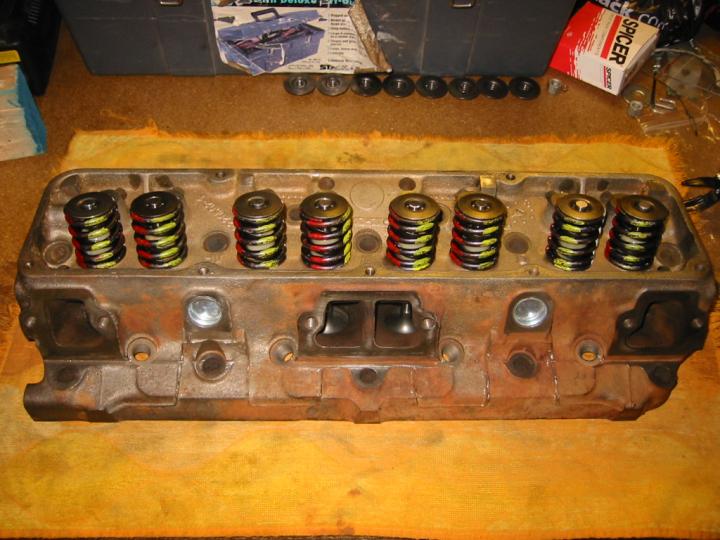
Valve/Spring Assembly
Assembly of the heads generally means installing the valves, seals, springs, retainers, and keepers. This is usually done before turning your attention to the rest of the short block so that once you’ve got your pistons installed, you can just bolt the heads on and install your lifters, pushrods, and rocker arms.
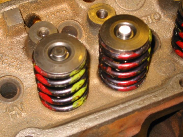
Before you begin installing the springs, you need to check your valve tip length. This is especially important if you’ve had any valve seat work done, such as a 3-angle job or replacing the valve seats altogether. Factory spec, according to my machinist’s book (it wasn’t listed in my TSM) for valve tip height is 1.950-1.990″ from the spring seat to the top of the valve tip. Ideally, you’d like them all to be equal, but anything in this range will keep your rocker arm geometry correct. If your valves are outside this range, you either need to get new valves of a different length or (if too long) have the valve tips ground down to the correct height. I had a couple valves that were on the high side, but by swapping places with shorter valves, I was able to get them all into the acceptable range. My intake valves (using stock valve seats with a 3-angle grind) are all pushing 1.990″, while my exhaust valves (using newly-installed hardened seats) are all closer to 1.950″. The valve tip height will also affect your cam lifter preload, but more on that later.
Once the tips are the correct height, you should also verify that the springs’ installed height is correct. Factory spec is ??? 1-13/16″, or 1.8125″, ??? between the spring seat and the bottom of the spring retainer. Check this by installing the retainer and keepers onto the valve and then measuring the height. I found some variance in the thickness of my retainers, so swapping retainers from taller valves to shorter valves allowed me to get everything within spec. If you’ve got a valve that’s too tall, you can shorten the spring height by adding a spring shim on top of the seat. Once you’ve gotten all these heights within spec, be sure to keep each retainer & keepers with the valve & cylinder on which they were tested!
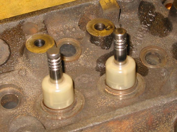
Nylon seals
When you’re done checking heights, it’s time to install the seals. Lube each valve stem with clean motor oil before inserting it into its guide. My gasket kit came with two packets of seals: nylon (whitish plastic) and polyacrylic (black rubber). Both are umbrella seals, which attach themselves to a mostly-fixed point on the valve stem and merely prevent excessive amounts of oil from splashing onto the valve guide. Positive lock seals are also available which attach to the valve guide and prevent any oil from making it into the guide, but you can only use these with bronze guides. Cast iron guides (which I have) need the lubrication provided by the oil that creeps in under the umbrella seals. Many engine builders don’t even bother putting seals on the exhaust guides, because the exhaust ports are always under pressure, and this pressure tends to force out any oil that may try to creep into the guide. Exhaust seals don’t hurt anything, so I installed them anyway while I was in there.
The primary differences between the nylon and poly umbrella seals are durability and ease of installation. The poly seals are much easier to install (just push them on by hand), but they don’t hold up as long. I opted to install the nylon seals (the same type that the factory used). They’re a press fit, which means you can’t just push them on by hand. The solution was to heat up a small pot of boiling water and toss the seals into the pot for a few minutes. (If you must use your wife’s good, non-stick cookware, do this after she goes to bed and be careful not to scratch it.) The heat will expand the seals and make them easier to install. Once they’re sufficiently warm, pull them out one at a time (not with your fingers!) and tap them onto the correct valve using a hammer and the provided install “tool” (a round plastic tube that fits over the valve stem). The final location isn’t critical, just get the bottom of the seal about 3/8″ from the spring seat. When the valve cycles, the seal will get pushed upward to the necessary height.
Now for the hard part: installing the springs. If you’ve got variable rate springs whose coils are closer together at one end than the other, the tighter windings go closest to the head. Place the retainer on top of the spring and break out your spring compressor. There are various types of compressors. Mine is the type that looks like a huge C-clamp and must be used with the head removed from the engine. It required quite a bit of force to squeeze the compressor’s handle 16 times, and I found that folding up a rag and placing it inside the palm of the glove I was wearing helped cushion the force and reduce the bruising on my palm. Use the compressor to squeeze the retainer and spring down far enough that you can slip the pair of keepers into their grooves on the top of the valve stem. My compressor had barely enough travel to allow this. Once the keepers are in place and the spring compressor is removed, tap the retainer on the top and sides a few times with a hammer to make sure the keepers are seated properly inside the retainer.
I forgot to install the seals on one of my heads the first time, so I had to remove all the springs and install them a second time. That wasn’t fun, but at least I’ve got my technique down pretty good by now.
Installation onto Block
This was the fun part, because I finally was starting to see my baby coming together. The first step — preferably done before you install the cam, crank, and pistons — is to clean off the head bolts and clean out all their holes. It’s important that the threads are clean, because bits of debris will cause inaccurate torque readings when you bolt the heads on. I used a tap to chase all 28 bolt holes and blew out the leftover crud with compressed air. That last part can scatter little bits of rust and metal all over, which is why you ideally want to do it before you install the pistons. I neglected this step until just before dropping the heads on, so I had to fill the cylinder bores with rags to keep the debris out and then wipe them down afterward. The head bolts themselves are a little easier. A wire brush chucked into a drill will clean them off fairly well, but I also chased the threads with a die to get them really clean. They threaded into place smooth as silk when I was done.
The next step is to wipe down the mating surfaces of the heads & block with solvent to get off the last bits of grime. If the cylinder walls have gotten dirty, wipe them out and then re-coat the walls with clean motor oil. If your engine stand will allow it, rotate the stand so that the head you’ll be working on is perfectly horizontal. This makes assembly easier and reduces the likelihood that a head will fall to the floor if you don’t get it lined up right on the locating dowels.
Unless the instructions in your gasket set tell you otherwise (my Fel-Pro set included no instructions), coat both sides of the head gaskets with adhesive sealant (not RTV). You can get this stuff in a spray can, which makes application easier (but messier), or you can get it in a bottle with a brush applicator, which is what I got. I think the brand name was Prima Seal or something like that. This stuff sets up as a sticky brown goo, so only put on a thin coat, then let it sit for a few minutes before installation. I hung mine on a nail to “dry” while I cleaned the mating surfaces (see above). When you install them, make sure that you’ve got them oriented the right way. My gaskets had a metal side and blue composite side, and the blue side had “TOP” stamped into it. Both gaskets were identical, so there was no front/back to worry about, but others may differ. The key is to not block any coolant passages or bolt holes. Double check this by holding it against the head before you apply the adhesive.
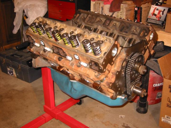
Heads installed on block
Once the gasket’s on, set the head onto the locating dowels, pound it down to the block deck with your hand, and quickly thread a couple of head bolts into place just to make sure it doesn’t slide off while you’re not looking. Coat the threads with extreme pressure assembly grease to act as anti-seize when torquing them down. The head bolts on an AMC V8 are two different lengths. The longer ones go inside the rocker area under the valve cover, and the shorter ones go down on the side by the spark plug holes. Torque all the bolts to 40 ft-lbs, starting in the center and working your way outward. Then torque them all to 80 ft-lbs, then finally 110 ft-lbs. This gradual, uniform pattern ensures equal pressure on the head gasket and prevents uneven loading or cracking of the head.
Once both heads are on, level the engine and install the valve lifters. Lube the inside of the lifters by squirting clean motor oil in through the hole on either the top or the side, and keep pumping until the oil comes out through the other hole. I found going in through the top to be easier. Smear oil around the outside of the lifter, and coat the base of the lifter with the same moly lube that you coated the cam lobes with. Drop them into their bores in the valley between the heads.
Now inspect and clean your pushrods, if you’re reusing old ones. Make sure the center oil passage is clean and that they’re not bent. Roll them along a flat surface, and if you can fit a .008″ feeler gauge between the rod and the table top, the pushrod needs replacing. If you’re reusing your old rockers, lifters, and pushrods, then be sure to keep your pushrods in the same location and orientation that they originally had, since the pushrod ends wear together with the rockers and lifters. If you replaced the rockers and lifters like I did, then location doesn’t matter, and you should put the more worn pushrod end (which was probably the rocker end originally) down into the lifter this time.
Rockers installed
Now it’s time to install the rocker arms and bridges. The original bridges were cast metal pieces that had rounded bottoms where the rockers rotated. New replacements have a stamped metal bridge which attaches to separate pivot points for the rockers. The newer pivots also have oil grooves to help lubricate this high-friction area, while the old ones were smooth. You install the rockers on each cylinder, rotate the crankshaft so that the cam is on its base circle and the lifters are as low in their bores as possible. Lube the pushrod tips, the valve tips, the bottom of the pivots, and the bolt threads with extreme pressure assembly grease, then bolt the rockers and bridge into place and torque the bolts to 19 ft-lbs. There’ll be more adjustment to come later, but just get them all on first so that the lifters can bleed down for a few minutes.
More about lifter adjustment later…
Miscellany
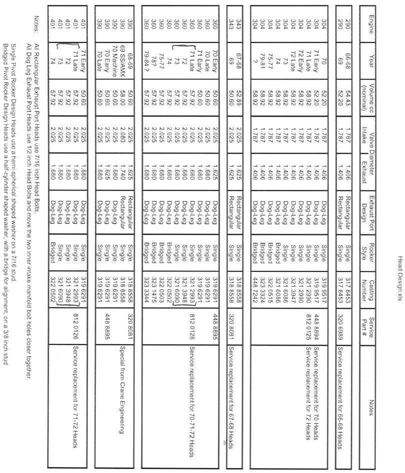 This chart, compiled by Frank Swygert, lists AMC V8 head casting numbers for most years of AMC heads. It comes in handy when trying to identify unknown heads.
Do you like this site?
Help me keep it going by throwing a few pennies my direction.
![]()
![]()
![]()
![]()
Links on this page to Amazon are part of an affiliate program that helps keep Jedi.com operational.
Thank you for your support!
That’s really cool that getting a 3-angle valve will really help your cylinder heads’ air flow. It seems like it would take a lot of time to actually recondition a cylinder head. If you didn’t like to tinker with your car then it would probably be a good idea to find someone who could do it for you.