Friday, 9 April
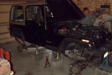
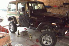
That night after work & dinner, I started tearing into it. I put the Jeep up on jack stands first. The six 17″ stands I borrowed were too short to get the tires off the ground, so I had to set them on cement blocks (against David Rush’s advice). I also had two 24″ stands, so I put one under each bumper to help stabilize things. I got the rocker panels 24-3/4″ off the ground, which was 5.5″ higher than before and 6.5″ or so higher than stock. The Jeep really looked tall then, so it was hard to believe that the SOA lift and new 33″ tires would actually lift the Jeep 2″ higher than where it currently sat on the jack stands!
Friday’s tear-down consisted of removing the shocks, axle vent hoses, front track bar, and front driveshaft. I beat on the pitman arm retaining nut off and on all night with my new 600 ft-lb Ingersoll-Rand 2131 impact wrench and liberal amounts of PB Blaster, but it wouldn’t budge. I’ll try heating it with a torch tomorrow morning. That impact wrench is already proving its worth. I’m very glad that I shelled out the $160 to get it before I did this lift. My low-power air ratchet is also quite handy.
Saturday, 10 April
I got started around 9:30am. I’m really glad I waited to do this until I got my garage insulated and ready to use. It’s cold and windy this morning with thunderstorms likely. Mark Vogel, a friend who recently bought his first Jeep (’94 YJ) and is excited to learn all he can, has volunteered to help me with the heavy stuff. He showed up around 10am. I put him to work disconnecting the brake lines — a task which turned out much more difficult than I originally imagined. I didn’t have a flare nut wrench (3/8″ is needed), so we tried using a normal open end wrench. Two of the five flare nuts unscrewed normally after liberal application of PB Blaster. A third wouldn’t spin on the hard line, but we were able to unscrew the soft line by rotating it around the flare nut. The upper end of both front lines were frozen solid, and by the time I finally broke down and bought a flare nut wrench, the frozen nuts were already stripped beyond repair. I decided to just cut off the old flare nuts and re-flare the front lines with a borrowed flare tool.
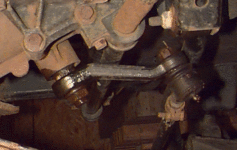
While Mark disconnected the brakes, I concentrated on removing the steering pitman arm. As expected, a little heat from a mapp-gas torch allowed the impact wrench to remove the retaining nut fairly easily. I then set out to pry the pitman arm off the steering box shaft using the puller I borrowed from Parts America. I had doused the arm in PB Blaster quite a bit before starting, but when I cranked for all I was worth on the puller with an 18″ breaker bar, all I succeeded in doing was breaking one of the jaws off the puller. Fortunately, I’ve got a friend that Parts America that swapped me for a new puller at no charge. I took it home and promptly proceeded to break it as well, despite excessive use of PB Blaster and a BFH.
I gave up on that for the time being and moved on to unbolting the axles from the springs before lunch. Just as we were finishing lunch, Chuque Henry showed up to help for a few hours. We made use of the extra man power by pulling the axles and bolting them up under the axles. Since my new rear spring perches were taller than the old ones (3/4″ vs 3/8″, I had to get new, longer U-bolts. The front bolts were still OK. The front spring retaining plates had to be swapped left-to-right to keep the sway-bar mounting pins in the right spot. The center pins that hold the leaf packs had to be reversed since the perches were now on the bottom. I had hoped to swap my leaf packs front-to-rear since the rears were sagging a bit more than the front, but a stubborn spring hanger bolt delayed that til another day. Getting it out will probably involve destroying the bushing, so I’ll probably wait on that until I upgrade to new poly bushings. Since my welder was temporarily out of service, we just bolted the axles in place for the time being. I’ll weld the perches in place later. Technically, my Jeep was now SOA. Too bad we were still a long way from done.
Sunday, 11 April
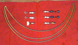
We started the day by driving up to Omaha to buy new brake lines. What to do about new brake lines was probably the biggest question I had when creating a shopping list for this project. Many places sell extended brake lines, but most are geared toward 4″ lifts. My net lift (SOA plus my existing add-a-leaves) would be 6-7″ over stock, so most pre-made brake lines would be much too short. I thought about just moving the hard-to-soft brake line fittings from the top of the frame to the bottom, thereby requiring shorter soft lines and allowing me to use relatively cheap, pre-made lines. In retrospect, this is probably what I should have done, because it would have been much cheaper. However, I opted to make custom, braided stainless steel lines of the exact length I wanted using components from Earl’s Performance Products purchased at Sack’s Hardware up in Omaha. These components are good, but they ended up costing nearly double what shorter lines would have. If I hadn’t driven an hour each way to get to Sack’s (thinking they’d be cheaper), I probably wouldn’t have bought them. When the dust had settled, I had spent $152 on new brake lines. My rear line is 26″ and my front lines are each 30″, not including the fittings on each end.
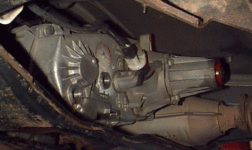
I then decided to tear into the Currie slip yoke eliminator kit while I still had good daylight to work by. The instructions Currie ships are excellent, and include photos (not just line drawings) for each step of the way. They do leave out a couple details for which I had to consult the factory service manual.
- Be sure to drain the case first. Even after draining through the plug, you’ll still get more ATF running out every time you unbolt a new piece of the case. Have a large-mouth container handy.
- You really don’t need to remove the transfer case from the Jeep, especially if you’ve already got a significant lift. The biggest problem with this is that you need at least 9″ or so of extensions to get your socket up to the front output yoke nut. A short-handled impact wrench works even better, but I had to thread the air hose up over the tranny. When you remove the yoke, remember to save the little rubber seal that’s shaped like a cross section of the splined output shaft. At first glance, it looks like a hunk of dried black RTV. You’ll need to put this back on when you reassemble the case.
- When they say you need a “good set of snap ring pliers,” they don’t give a hoot about the quality of the pliers. What they mean is that you need a set whose jaws can open extremely wide (about 1.25″). The snap rings you’ll have to deal with are not the type with holes to grab onto. They’re more like C clips, which means you really want the kind of pliers that have paddles on the end rather than pins. Battling these with my small snap ring pliers took more time any anything else, and eventually proved futile.
[Update: Several years later, I found that Craftsman now makes some lock ring pliers that are perfect for the job.] - After unbolting the rear bearing housing from the case, you should break it loose from the seal by hitting it with a hammer to rotate it clockwise. Don’t hit it straight sideways, and don’t use a screwdriver to pry it away from the case.
- What kind of brain surgeon decided to bolt the NP231 case halves together with seven 15mm bolts and one 10mm 12-point bolt? 12-point? Why? Of course, the odd ball is on the very top center of the case, so your access to it with a box end wrench is quite limited. Once it came loose, I was able to finish the job with an 11mm, 6-point socket.
- Once you’ve unbolted the case halves, you still have to pry the rear half loose from the seal. There are two slots on the edge of the front half of the case, at about the 10 o’clock and 4 o’clock positions, into which you can insert a large screwdriver and pry the halves apart. I found that only the 10 o’clock slot allowed enough clearance for my screwdriver to pry effectively.
-
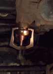
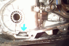
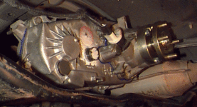
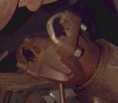
When the case halves came apart, a 1.5″ magnetic washer fell out. This disk belongs here (photo at right), in the slot in the lowest part of the case, just below the front output shaft.
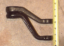
After battling the snap rings for a while with my tiny pliers, I finally gave up for the night and moved on to the pitman arm, now with my third pitman arm puller (this time from O’Reilly’s, but the same brand puller that Parts America gave me). Despite warnings about frying the seals in the steering box, I heated the arm up with my mapp-gas torch, then bathed it in PB Blaster and beat on it severely with a BFH. Beware — the penetrant that runs off the pitman arm will be hot. I didn’t even bother trying the puller at first; I just heated, squirted, and beat on the arm. While doing this, the tie rod vibrated its way free of the lower end of the pitman arm and fell to the ground, thereby eliminating my need for a pickle fork to pry it free. I let it sit for a few minutes while the penetrant did its thing, then I repeated the process. After the second iteration, I put the puller on and started cranking with a 12″ socket wrench. I didn’t pull to hard since a broken O’Reilly’s puller would have cost me considerably more than the broken Parts America pullers did. Just when I was about to give up and apply more heat, I heard a pop. My first reaction was “oh great, there went my third puller,” but when I looked, I found that the pitman arm had come down 1/8″. A few more cranks had it completely off. Even through leather gloves, the pitman arm was quite hot. I squirted it and the steering box lightly with water, and both produced steam.
Tuesday, 13 April
Other obligations kept me out of the garage on Monday, but on Tuesday I found a set of slightly larger snap ring pliers and finished the SYE kit installation. The new pliers weren’t perfect, but they worked well enough. The rest of the installation went just like Currie said it would, except:
- I swapped steps 18 and 19 by installing the new output bearing in the bearing housing before I bolted the housing back onto the t-case. It seemed much easier this way. A rubber mallet is invaluable for the latter half of the installation, BTW.
- Currie’s instructions don’t tell you to re-install the front output yoke. Be sure to place the rubber gasket back on the end of the output shaft before you put the nut on. The FSM says to tighten the nut to 110 ft-lbs. Due to its inaccessibility with a torque wrench, I just set the impact wrench on setting two and called that good.
- Don’t forget to refill the t-case with 3.25 pints of ATF.
[UPDATE: Some time later, I had to replace the oil seal at the rear output of the SYE kit. The Currie SYE kit uses the same seal as the stock YJ t-case, which is National (Federal-Mogul) part number 473317. It’s 1.687″ ID, 2.328″ OD, 0.312″ deep.]
I also finished torquing down the rest of the suspension to specs and reconnected the steering. Due to the increased angle of the drag link, my steering wheel is no longer centered when the wheels point straight ahead. The drag link length will need to be adjusted to fix that.
When I attempted to reconnect the front track bar with the new extended bracket from RE, I found that the bolt they shipped was too big to fit through the holes in the bracket. Looks like somebody grabbed it out of the wrong bin. 7/16×2.5″ should fit better than the 1/2×2″ that they sent me.
I managed to get one of the flare nuts free on the hard brake lines (on the rear axle) by briefly using the ever-useful torch and PB Blaster. I can now state from first-hand experience that brake fluid is flammable, but fortunately not explosive. I didn’t want to use the torch on the front lines for fear of screwing up the paint on the fenders. Clearance down there is at a premium.
Thursday, 15 April
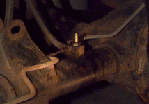
I got the SS brake lines assembled. The first fitting was a bear, but they got easier once I got the hang of it. After you include the length of the fittings (3″, something I’d forgotten to consider when buying the line), the rear line ended up being 29″ (13″ longer than stock) and the front lines were 33″ (12″ longer than stock). That’s great for the rear, since the new T fitting on the axle points it straight up and the line stays up and out of the way nicely. The front lines aren’t installed yet, but I have a feeling it’ll be a little trickier keeping them away from the tires at anything less than full droop. On the recommendation of the guy I bought them from, I got AN-4 fittings. He said AN-3 was only used for motorcycles and other small stuff, but most of the SS lines I’ve seen on other rigs look more like the thinner AN-3 than AN-4. The AN-4 seems a bit more inflexible than I’d prefer, and it seems a bit larger than the lines that come with other kits like RE’s.
Saturday, 17 April
Well, I can safely say that dealing with the brake lines was by far the biggest headache of this whole project. I cut off the old, goobered-up flare nut from one of the front hard lines. Turns out the flare tool I borrowed only did single flares, so I borrowed one from Parts America that did double flares. I also found that the soft line fittings I was sold by Sack’s weren’t meant for inverted flare hard lines. I had to run to Speedway Motors and four other parts stores later on to buy the right fittings.
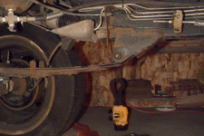
At least I was able to get the emergency brake cables reconnected. The passenger side cable was disconnected from it’s bracket on the bottom of the tub and re-routed over the leaves and through one of the rubber exhaust brackets en route to the bracket on the driver’s side frame rail. The driver’s side cable also goes over the leaves, but otherwise follows the OEM routing pattern to the frame bracket. This still isn’t long enough under full droop, unfortunately. I only need a few more inches, since the frame bracket is very near the spring hanger. After several wheeling trips, I finally drilled a new hole in the bracket about two inches below the OEM hole. This is about as close as I want to get to the bottom corner of the bracket. The holes are 9/16″, so I had to ream out a 1/2″ hole in order to make the cable fitting fit.
I also managed to lengthen the drag link so my steering wheel is more or less straight again. Just loosen the clamps at each end where the rod ends screw on, bathe the threaded portions (including the slot that the clamp squeezes) with PB Blaster, and start twisting the middle section of the drag link with vice grips. The front of the bar must go downward. It’ll be a bear at first, but it eventually gets easier. I needed to turn mine several full revolutions to get the extra length I needed — approximately 1/4″ at each end.
Tuesday, 20 April
I finished installing the front brake lines last night. I’ll bleed them as soon as help’s available. I ended up using vice grips to break loose the flare nut on the driver’s side and then used the same to reattach it to the new lines rather than cutting and reflaring, like I did on the passenger side. It was just easier. I still need to rig up some sort of bracket to secure the mounting point to the frame, but that shouldn’t be too difficult.
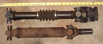
I also got the new CV rear driveshaft and installed it last night. Tom didn’t charge me for the D35 yoke U-bolt conversion, for which he’d quoted me $4 over the phone. The U-bolt conversion was pretty painless. The threaded holes in the stock yoke are a shade larger than 3/16″. I gradually reamed out the holes using 7/32″, 1/4″, and finally 5/16″ bits to make room for the larger U-bolt shafts. They definitely look stronger than those puny little straps that used to hold the stock driveshaft on. In Tom’s words, “Why do they bother putting eight beefy bolts on the flywheel if they only have those four tiny screws on the driveshaft yoke?” If you want to do this swap yourself, Tom says that the U-bolts are Spicer part number 2-94-58X. Be careful not to over-tighten the nuts on these U-bolts. I pushed one too far and partially stripped it.
Wednesday, 21 April
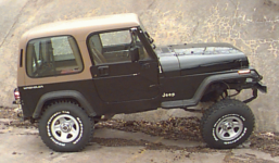
Chuque came over to help. We started by picking up four of the five new BFG 33×9.50’s from Sam’s and having them mounted on my OEM rims. The fifth tire wasn’t in yet — maybe it had to come from a different warehouse. Those beasts are much heavier than the 225/75R15 Goodyear Wranglers that came stock. I hope my wife never has a flat by herself, because she’ll never get the bad tire back up on the rack. When replacing the wheels on the Jeep, we found that the stock scissor jack is just barely still tall enough to raise a tire off the ground. My 48″ Hi-Lift is plenty tall, but it gets very tipsy when jacked up that high. The new tires do a better job of filling the wheel wells, but I think 35×12.50’s would look much better in there. I’ve still got 8″ between the top of my tires and the bottom of the fender flares and 27″ below my rocker panels. The bottom of the door opening is just shy of crotch level for me (I’m 6’1″); if I were 2″ shorter, I’d be singing soprano after trying to climb out those first few times. What ever possessed me to put 7″ of suspension lift on a YJ, anyway? I’ve created a monster. I feel like Dr. Frankenstein — I had such good intentions when I started, but the project took on a lift of its own and may now be more than I can handle. I might lose the add-a-leaf someday. I do like the 70-degree approach angle, though.
Next, we bled the brakes. Remember that brake fluid is very hard on paint. Every effort should be made to prevent the fluid from getting on your paint, and that includes remembering to wrench-tighten those last couple brake fittings that you only finger-tightened the night before. Once you’ve cleaned up your mess, resume your pump-loosen-tighten-release sequence, beginning with the brake farthest from the master cylinder and working your way closer. When it seemed that we weren’t making much progress with the front right brake, we jumped ahead to the front left brake and cleared most of the air (there was plenty of it) out of that line before returning to the right side. While I haven’t ramped it yet, it appears that my front brake lines are way too long — a fact Chuque never stopped taunting me for while helping me bleed the brakes.
By now it was too late & dark to go ramp it, since my PPW alternator was still in the shop being repaired (that’s a tirade for another day) and I didn’t want to run my headlights off just my battery. I did fire it up and drive it out onto the street beside my house so I could hose off all the brake fluid we spilled. With no track bars, sway bar, or shocks, the Jeep was quite tipsy. I still have 3-4″ between my hard top and my garage door, so I still have use of the garage. While pulling up to the curb, I heard a loud noise and the Jeep suddenly lurched to the left. Further inspection revealed that I hadn’t quite torqued down the U-bolts around the front springs, and so my front axle had spun loose and the pinion had climbed to about 45 degrees. Fortunately, the front driveshaft wasn’t attached yet, so no damage was done. It felt good to finally drive it again after 12 days, even if it was for just 50 feet.
Thursday, 22 April
We tried to go ramp the Jeep during daylight. Just out of the driveway, the front axle went pinion-up on me. That’s twice that’s happened due to the force of turning while slowly accelerating. We straightened it out, then started to pull back into the driveway and ramp it on a sturdy plank that was resting in the back of Chuque’s D90 (love that 1-ton load capacity). As soon as I hit the ramp, the extra torque twisted the rear axle pinion-up. I’ve decided that it’s impossible to torque those U-bolts down enough to hold the axle in place under any kind of load. Before you go out on the street, you need to at least tack weld the perches in place. If you later decide you don’t like the pinion angle, grind off the weld and reposition them.
The rear U-bolts I got were much too long to get a deep-well socket on the nuts (7.5″ tip-to-bend), so I spent the rest of the relatively-short evening shortening them an inch. I swear, those things must be made of hardened steel. I went through a couple hack saw blades, an ounce or so of cutting oil, and a noticeable chunk of my grinding wheel just cutting eight bolt ends.
Saturday, 24 April
I planned to weld the spring perches onto the axles today so I could finally ramp it. Numerous friends and one stranger stopped by to talk for a while, so I only managed to get the front axle done. Correctly positioning the perches side-to-side along the axle was the hard part. I must have eye-balled, measured, and re-adjusted things over a dozen times before I was happy. I ended up dropping the rear pinion about 0.5 – 1 degree below stock to get just a hair more caster. Six months later, I’ve seen no problems. My post-lift wheel alignment showed that the caster was now set at 6.86 degrees on the left and 6.89 degrees on the right. The acceptable range for a manual tranny is 5.25-7.25 degrees.
I also found out that I can’t stick weld worth a crap. The fact that I couldn’t get my face anywhere near the perches while wearing my welding helmet and therefore did most of the welding one-handed didn’t help any. I eventually got a number of large tack welds that look like they should hold the perch in place. When welding the axle, it’s very important to just weld a little at a time and cool the axle tube off with few squirts of water in between welds. If you weld for too long, you’ll boil your gear oil and toast your seals.
Sunday, 25 April
I had a boat-load of stuff to do today, so I got up ridiculously early and was in the garage by 7am. I got the rear perches welded in place with about the same difficulty as the fronts. I think I finished around 11am. Note: it’s very difficult for one person to slide an axle sideways while it’s weight (though not the vehicle’s) is resting on two tires. After much measuring and adjusting, I finally got the perches setup so the pinion was about two degrees below the driveshaft angle. On the test drive, I felt a slight vibration when braking, probably because the pinion was being forced down (and outside the 3-degree optimum window).
The track bar relocation bracket that I got from Rubicon Express wasn’t quite right for a lift as big as mine (and probably not for their own SOA kit, I’d imagine). The track bar is shorter horizontally now, so the bracket mounting hole needed to be farther to the left than it was. I ended up grinding a bit off the side of the lower lip of the bracket so it would bolt to the OEM bracket at an angle. This allowed it to reach the track bar, and appears to have cured most of the bump steer that I got when driving without the track bar. I never imagined it would be so bad without the track bar, and will never consider driving faster than 10 mph without it again.
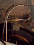
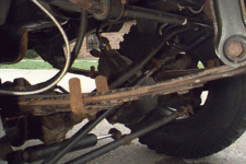
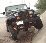
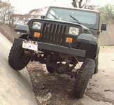
Once everything was in place, I headed out for an extended test drive on back streets. It bounces pretty good without shocks, so I tried to keep it below 25 mph. Other than that, it’s not bad. I finally got to ramp it on a 50-degree retaining wall at a nearby parking lot. As expected, my brake lines and vent hoses are way longer than necessary (photo at right). I could easily chop 4″ off them and still be OK. If I’d remembered to include the 3″ worth of fittings when measuring for new brake lines, I’d have probably come out OK. The driver’s side emergency-brake cable is way too short. I’m losing up to an inch of travel on that wheel due to it. I’m going to try rerouting it a little, but I may have to replace it with an XJ cable or something before I go wheeling. While I didn’t try it, I’m sure that disconnecting the front track bar would increase the articulation noticeably. The rear track bar was removed years ago, and had a similar effect.
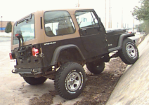
Although the tires look too small for the lift when the Jeep is sitting in the driveway, that changes under full articulation. The rear tires do indeed stuff up inside the fender flares. I’ve still got room for 2″ taller tires (35’s) before I hit the fore and aft body panels inside the wheel well, assuming the tires are no wider than 10.5″. To go wider than 10.5″, I’d have to drop down to 31″ tall tires to avoid trimming the front of the rear fender flare.
With the front wheels pointed straight ahead, I’ve still got gobs of clearance, even under full compression. I could probably fit 35″ tires without rubbing. With the wheels turned at full lock, I’m already rubbing the springs. The noise of those big lugs clipping the springs really freaked me out until I realized what it was. Time to open up the steering stops, I guess. FYI, these tires are mounted on OEM 15×7 wheels with the stock 5.25″ backspacing. A couple years later, I installed new wheels with 3.75″ backspacing, which fixed the problem with room to spare.
Thursday, 29 April
I finally ordered the shocks on Monday. Calls to several mail-order places and Rancho tech support determined that I needed 9012’s up front and 9126’s in the rear. 9126’s are the same length as 9112’s, but are supposedly valved lighter and therefore better for a lightweight vehicle. I used this Rancho 5000/9000 shock guide to choose my models, and the shops confirmed that no more appropriate models had come out since that list was posted. Since delivery time was most important, I found myself shopping for 3-day shipping prices. Of the several places I called, only a couple had my models in stock, and of those, 4 Wheel Parts Wholesalers had the best price. Total with 3-day UPS shipping was $218.08.
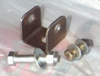
They arrived on Thursday as expected (a refreshing change from the rest of this project) and I set about installing them that evening. First, I had to make new upper mounts for the front shocks. The pin-style mounts that the OEM shocks use are uncommon enough that Rancho doesn’t make very many models like that. The 9012’s were the only Rancho shock that was even close to long enough, and it used eyes at both ends. Rubicon Express makes shock adapters, but I’m cheap and decided to make my own. A friend had grabbed me a length of 2″ square tube with a 1/8″ wall a while earlier. I simply cut two 2″ long sections (1.5″ would have worked better) and then cut off one side of the square to form a U. A 1/2″ hole was drilled in each side of the U for a bolt to mount the shock and in the base of the U to mount the adapter to the existing shock mount. The shocks came with a handful of bushing sleeves of various sizes. After mounting the bottom of the shock, the best remaining sleeve required an M12x60mm (12mm diameter x 2.25″ long) center bolt.
While the brackets sound simple enough to make, they actually took several hours and were more trouble than I expected. If I’d been thinking when I put in the rest of my RE order, I probably would have bought their weld-on mounts for $10/pair and just bought the rest of the bolts at the hardware store. It’s not worth the shipping costs to get just the mounts by themselves, though. You can read about my other shock mount modifications here.
Some years later, the polyurethane bushings in my RS9000 shocks began to deteriorate. Read about how I replaced them.
[Last updated 4 May 2005]



hello very good job you did I would like to ask you if you have a side image with 31s tires.